Dear Reader,
We are pleased to let you know that the base infrastructure of the Techtile research and testing infrastructure[1] is nearing its completion.
In this newsletter we highlight one of the key elements of the infrastructure, i.e., the innovative powering design based on PoE.
Furthermore, since the base setup is nearly finished, it is time for an official opening. Find out when, where and what in this newsletter.
The Techtile team, September 2021
Techtile revisited
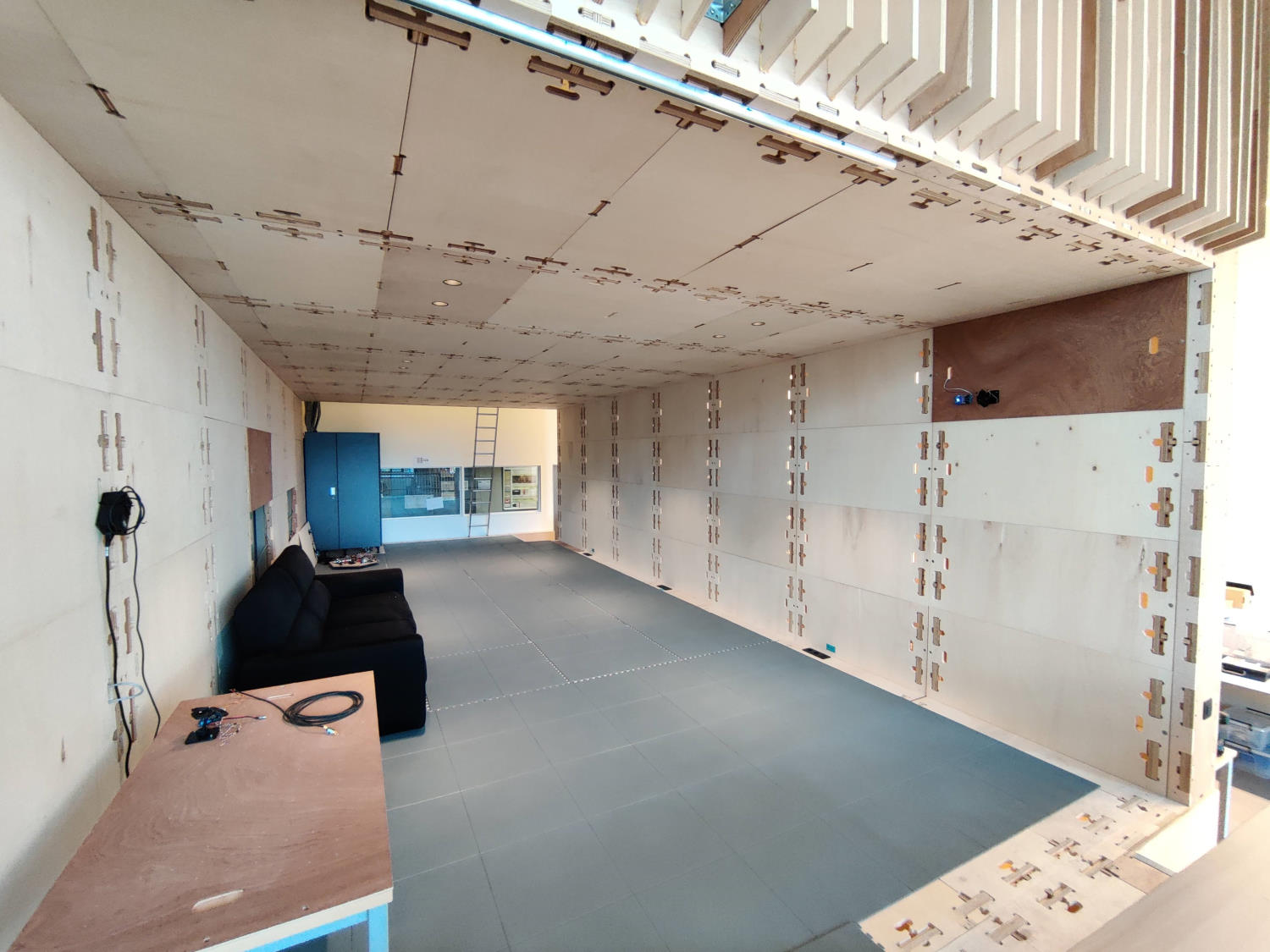
The Techtile measurement infrastructure is a multi-functional, versatile testbed for new communication and sensing technologies relying on fine-grained distributed resources. These resources are interconnected and integrated in 3D in the environment. The facility enables experimental research on hyper-connected interactive environments and validation of new wireless connectivity, sensing and positioning solutions. It allows researchers to develop the ICT technologies for emerging and future applications, for example efficient living and smart working and care environments, autonomous devices in logistics and Industry 4.0.
Techtile consists of a data acquisition and processing equipment backbone and a fabric of dispersed edge computing devices, radios, sensors, and LED sources. These bring intelligence close to the applications and can also collectively function as a massive, distributed resource.
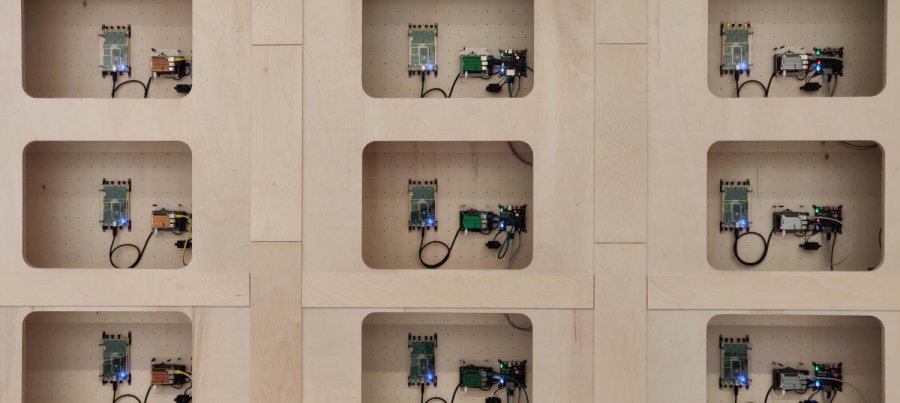
The structure hosts 140 detachable tiles of equal size on the walls, floor, and ceiling. A versatile set of equipment is mounted on these panels, effectively embedding the electronics into the room. All tiles will be connected in an ‘electronics weave’, where each tile will be equipped with a local computer. Read our previous newsletter to find out more about what specific electronics are in the testbed. The “Primer on Techtile” provides more details.
Grand opening – Techtile says “hi”
On October 21st we officially open our research infrastructure to the public. We invite you to come have a look at what we have built. For companies and organizations that are interested in using Techtile for one of their experiments, we provide a technical tour of the facility. This technical introduction takes place from 16h until 18h.
Starting from 18h, we have an official opening for everyone who is interested in DRAMCO and our research. We will make sure that nobody goes hungry or thirsty.
Interested in meeting our researchers and new infrastructure? Register for this grand opening event via this webpage.
Powering the RadioWeaves
To power all tiles, we have opted for Power-over-Ethernet (PoE). This effectively reduces the number of cables needed. At the same time, attaching and detaching the panels, becomes easier.
The latest IEEE 802.3bt PoE standard supports power transfers up to 90 W and is backward compatible with the older IEEE 802.3af/at standards. In order to facilitate the – at this time unknow – power requirements of any future application, this standard has been chosen over the other older standards.

The figure above shows a minimal PoE setup. A Power Sourcing Equipment (PSE) injects 48 V on some or all of the Ethernet pairs. The PSE is typically a rack-mounted unit. The Powered Device (PD) decouples data and power and converts the 48 V to a desired voltage level to be used locally.
We have designed a custom PoE PD board to power all the electronics on the tile. The board’s main functionality is to separate the power and data traffic from the ethernet cable. In this specific setup, all 4 pairs are used to deliver power to the PD. The ON-Semi NCP1096 PoE-PD Interface controller negotiates with the PSE to establish the power link. The controller provides a detection signature, classification handshaking, inrush current limitation and operational overcurrent protection.
Four LEDs give the user information about the PoE status:
- PG (Power Good LED) indicates the flyback converters can be enabled;
- LCF (Long Classification Indicator) is on when the PSE is categorized to IEEE 802.3bt standard (PSE Type 3 or 4);
- NCM and NCL indicate what class has been negotiated with the PSE.
Powering devices
A host of on-board connectors allows users to power the edge processing device and USRP on each tile, as well as other equipment for future experiments and setups. To that end, the 48 V is converted to a lower voltage.
- An on-board flyback converter provides a stable 5 V output voltage and can deliver up to 4 A or 20 W of available output power. The flyback’s input voltage ranges between 36 V and 75 V, which exceeds the worst case PoE voltage swing (37 V - 57 V) that could occur in a typical PoE system. Hence, correct operation is guaranteed on all tiles, regardless of its specific cable length or power draw.
- An external DC/DC converter (e.g. 12 V or 24 V) can be connected to the PD board as well. Depending on the selected PoE class, this converter can deliver up to 50 W for applications that require more power, e.g., LED lighting, acoustic speakers or a wireless power transmitter.
Selecting the right PoE classification setting for each tile is a key part of the setup process. It is important to know the maximum power that each tile will consume. Not considering the maximum available power can result in a power failure.
The IEEE 802.3bt standard defines 8 power classes, i.e. class 1 up to class 8. All classes can be selected by changing the PoE class selector board. When no class selector is installed, the NCP1096 will select the default class 3, which corresponds with 13 W available for the PD.
Beside class 3, we provide a few other PoE class selector boards for our testbed: class 4 (~25 W), class 5 (~40 W), and class 8 (~70 W).

Power Sourcing Equipment
In order to power all 140 tiles, we rely on 9 Microsemi PD-96xxGC midspans, each with a power budget of 950 W. Four 24-port PD-9624GC and five 12-port PD-9612GC midspans provide a total power budget of 8550 W, to be distributed over 156 ports. This is the reason why we don’t put every tile in class 8 by default. Such a configuration would exceed our available power budget. Instead, tiles are by default in class 4 (approximately 30 W at the PSE side). This means a total of 4200 W of the available 8550 W is reserved to operate all the tiles. The remaining budget (approximately 50 %) can be used to put tiles in higher power classes, to power the more power-hungry applications such as VLC (Visible Light Communication), VLP (Visible Light Positioning), WPT (Wireless Power Transfer) systems, and many more.

Since all midspans support the Simple Network Management Protocol (SNMP), central control from the server is possible, allowing for example to power tiles on or off individually. This functionality is currently integrated with the ansible automation framework that will be used to update and control the software running on the tile’s Raspberry Pi computers.
Showing the power of PoE
To showcase an applications that demands more power, we have extended the standard elektronics of 1 tile with a wireless power transmitter. This transmitter consists of a series resonance circuit with a class D amplifier operating at 60 kHz.
A parallel resonance circuit with a full bridge rectifier and smoothing capacitor acts as a receiver. This circuit powers a LED matrix and, as a whole, serves as wall light.
Our plans for the next months
Next to showing the infrastructure at our opening event, we will start several experiments.
- Study of indoor RF energy harvesting for interacting with energy-neutral devices (PhD project)
- Investigation of the performance of indoor localization using ultrasound with a large number of distributed receivers (master thesis).
- Design and development of a 280-antenna system for next-generation wireless access (master thesis).
- A study of low-cost time synchronization hardware in order to support large-scale antenna systems (master thesis).
You can contact the Techtile team or contact any member of the Techtile team: